Casing is done to provide the support and to avoid unconsolidated sand, gravel and the loose rock fragments from falling off the wall of the well. This is basically done to avoid the destruction of the well shaft. The basic purpose of well is that it provides easy access to aquifer . Once a well is constructed for the pumping system, It then acts as the conduit, it bring out the water from aquifer at the surface.
Because of the high durability, strength and corrosion resistance, steel casing has been the most preferred material for the water wells. Also, steel casing has the ability to withstand very high temperatures that is caused by curing cement plaster.
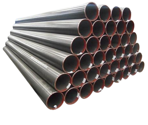
STEEL TUBES FOR WATER WELLS (CASING PIPES) CONFORMING TO IS: 4270/2001
This standard covers tubes for casing, driving, housing pipe with screwed and socketed butt joints, screwed flush butt joints and plain beveled end pipes for butt welded joints intended for water wells application having Grade of steel Fe 410 or Fe 450 to indicate minimum Tensile strength in MPa. There are different types of steel tubes used for water wells:
(a) Casing Pipe :
Casing pipe is a pipe which is used to protect the wells and the bore holes from collapsing.
(b) Housing Pipe :
Housing pipe is the upper portion of the case section of the well and serves as housing for the pumping equipment and is a vertical conduit through which water flows from the aquifer to the pump. It is water-tight and extends downwards from ground surface to a fade depth below the anticipated pumping water level.
(c) Drive Pipe :
Drive pipe is also a type of casing made up of seamless or welded mild steel pipes designed to withstand the driving force and to penetrate into the ground so as to protect the collapse of the movement of the loose formation which take place during the drilling operations.
Specification
| N.B of Pipe MM |
Outside Diameter |
Thick-ness | Nominal Weight Black Tubes Plan End |
|
|---|---|---|---|---|
| mm | mm | Kg/m | m/tonne | |
| 100 | 114.3 | 5.4 | 14.5 | 69 |
| 125 | 141.3 | 5.4 | 18.1 | 55 |
| 7.1 | 23.5 | 43 | ||
| 150 | 168.3 | 5.4 | 21.6 | 46 |
| 7.1 | 28.2 | 35 | ||
| 175 | 193.2 | 6.4 | 29.6 | 34 |
| 8 | 36.6 | 27 | ||
| 200 | 219.1 | 6.4 | 33.6 | 30 |
| 8 | 41.6 | 24 | ||
| 225 | 244.5 | 7.1 | 41.6 | 24 |
| 9 | 52.3 | 19 | ||
| 250 | 273.1 | 8 | 52.3 | 19 |
| 10 | 64.9 | 15 | ||
| 300 | 323.9 | 8 | 62.3 | 16 |
| 10 | 77.4 | 13 | ||
| 350 | 355.6 | 9.52 | 81.25 | 12 |
| 400 | 406.4 | 9.52 | 93.17 | 11 |
TOLERANCE
| 1. | Outsider Diameter | 1% |
| 2. | Thickness Welded tube Upto and including 406.4 mm |
+15% -12.5% |
| 3. | Weight Single Tube |
-8% +10% |